As noted before, I enjoy restoring these units to good working condition. The difference between these primarily-military units and the commercial shortwave receivers is quite remarkable. These are much easier to repair. They are designed so you can get into every nook and cranny (sometimes with some difficulty) so every part can be repaired. Here and Here and Here and Here and Here and Here and Here and Here and Here and Here and Here and Here are descriptions of units I restored and sold on eBay. For more information on Hammarlund and these great receivers, visit the
Hammarlund Historian web site.
|
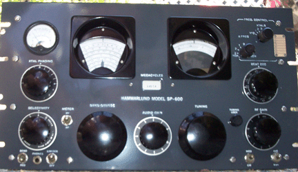
SP-600 Tibdibs
ABOUT THE CASEFair Radio lists a number of cases. I believe these are made by Hammond Manufacturing, which also makes many of the great transformers for these vintage products. I have used a number of these cases and can say they are of good quality and well worth the price. I haven't figured out how to get louvres in the sides or get a hinged, lifting top like the vintage cases had. Any suggestions will be appreciated. Also, these cases support the radio entirely from the front panel. The old cases had a shelf the radio sat on. I think the air circulation is better with the modern cases, but it does put a lot of stress on the front panel. The SP-600 has a relatively flimsy front panel, but I can't say that I have ever seen one distorted by supporting the radio. These old radios need as much air circulation as you can get. Note that for the SP-600, the case has to be unusually deep - greater than 16". ABOUT WASHING/CLEANING AN OLD RADIOPeople ask me frequently about how I get the chassis of the SP-600 so shiney clean. First off,
they are more shiney in the pictures than they are in real life. I take my cleaning technique
from Dave Medley. You can read about his technique
here. For me, the cleaning is just one part
of the restoration process, so I do not clean a radio unless I am ready to completely restore
it. My procedure goes as follows:
ABOUT THE CRYSTALSI have had a number of questions about the crystals in the FCU (Frequency Control
Unit) of the JX models. Getting a crystal is not a difficult process.
International Crystals
will be happy to sell you as many as you want, even in the antique HC-11 package, at
about $15 each, custom-cut to your frequency. You do have to get the frequency right.
It is not just the frequency of the station you are trying to receive. Here is a
reduced version of the chart to figure out the crystal frequency, given the frequency
of the desired station:
7.4 MHz to 12.05 MHz - add 3.955 MHz 12.05 MHz to 44.05 MHz - Add 3.955 MHz and divide by 3 (3rd harmonic) 44.05 MHz to 54 MHz - Add 3.955 MHz and divide by 4 (4th harmonic) You will also have to specify some other stuff. Use the following: Case: HC-6/U Mode: PARALLEL Parallel capacitance: 40 pf Resistance at Resonance: 200-1000 ohms (not critical, as high as is reasonable) Mode: fundamental, 3rd or 4th harmonic from table above Precision: 25 ppm (you can get better by paying more) Signal Level: 2-5 volts. Here is a little calculator that will compute the above formula for you: Desired Frequency in MHz: |
Scanned SP-600 ManualsOne of the most difficult parts of dealing with these old receivers is finding the appropriate manuals. Without schematics and other descriptions, it is a hopeless task trying to repair these things. Fortunately, there are a number of the original manuals still extant. They show up on eBay from time to time, or can be borrowed from old-timers (although the number of such is diminishing every year). Another problem is that most scans of these manuals are of relatively poor quality. I attribute this to the fact that high-quality scans take a lot of disk space, and it takes a fair amount of time to dress them up in Photoshop. I do not have a lot of manuals, but the ones I have, I have scanned in at high resolution. I manually descreened the half-tone images, since the automatic descreening doesn't work very well (seems like us DSP types should be able to fix that). Below are some of the manuals I have put together. The first three are from BAMA and are not of high quality. The rest are of very good quality, but are also quite large. The grandaddy of SP-600 manuals is TM11-851, the military manual on the R-274 and related receivers (N.B. - there was a unit made by Hallicrafters that was also called the R-274. That's in TM11-897. I have not scanned it - yet.). It is particularly problemmatic, since it has six schematics that are 14" by 60". I include scanned versions of these in the original form factor, but also a version that has each schematic as three 11"x17" overlapping sheets, so you can print them out (Kinko's can do this) and tape them together to get the full schematic. This manual only covers units up to serial number 4600 or so and does not cover the diversity receivers. There is a separate manual (see below) specifically for them. If for some reason you can't manage to download what you want, for $20 I will send you a CD-ROM with all these .PDF files on it. I prefer PayPal to jamminpower@earthlink.net, but you can just send me a personal check or whatever. Send me an email and give me your mailing address and I'll get a CD right out. Also, I learned that there are a number of readers that have no good way to get a printed copy of these manuals. As a service to my readers, I will print out and comb-bind a copy of any of these manuals for you for $15 each (postage to US included - more for foreign). The one exception is the big one - TM11-851. I have to charge you $45 for that one because of the size (200+ pages) and the difficulty of printing out the schematics. I print them as 3 11x17 sheets for each of the 6 schematics. I list below the original SP-600 manuals, Issues 1 through 6. 1, 2, and 3 are pretty similar, but 4, and 6 are quite different. Without explaining it, they describe various different models. For instance, the schematics in Issue-6 correspond to the JX-14 model (except that the wiring diagram in Issue-6 doesn't correspond with the schematics therein!). Well, there is also an Issue-7. But don't get your hopes up - it is a reprint of Issue-6. It was reprinted in 1966 (a decade after Issue-6). It does not have any additional information in it that wasn't already published in Issue-6. That being the case, I did not bother to scan it in. Same thing with Issue-5. I couldn't tell any difference with Issue-6, so I didn't bother. Also, I am always searching for originals of Hammarlund manuals - even the ones I have already scanned below. I have noticed that there are often different versions of the manuals, even though they are called the same thing. For instance, I know that there are two different versions of the JX-17 manuals. I only have one of them. And there are two manuals that are earlier than Issue-1 that are just called SP-600J and SP-600JX manuals. If you have any of these original manuals, please let me buy or at least borrow them for scanning. |
| Download 6MB |
Issue-1 From BAMA. This is the oldest of the Hammarlund-issued SP-600 manuals and it shows it |
| Download 10MB |
Issue-2 From BAMA. This one actually is reasonable, but the schematic doesn't have component values on it. A real pain. |
| Download 5MB |
Issue-3 From BAMA. This is the first one that is particularly useful. It does describe one class of the first few thousand of these that were built. These are the ones that have the linear E13, as opposed to the rectangular block E13. This may seem like a technicality until you get one with the block E13 on your bench. |
| Download 80MB |
Issue-4 My scan. This is the first manual that shows clearly the rectangular block version of E13. It actually has two separate sets of schematics and wiring diagram. One has the linear E13 and the other has the block E13. Also, the block E13 version has R72 and R73 going to the screen supply of V1, V2, V3, and V5. This is the infameous "7-wire" RF deck and is not compatible with any other RF deck. You can NOT swap this RF deck with any other unit. This form of screen supply was quickly abandoned, but R72 and R73 were retained in later units for the screen supply of the IF strip. |
| Download 89MB |
Issue-6 This one represents most of the later models except for the diversity receivers. I also included annotated versions of the wiring diagrams where I put the component values next to the part numbers. |
| Download 94MB |
SP600-JX-17 This one documents the "diversity" receivers. This is the most common unit that was made. There are significant differences from the other models. The 3.5 Mhz oscillator is a tuned-plate type rather than a tuned-grid type. The FCU has two boards in it and a torroidal transformer (which is generally broken into small pieces) with an RF connector on the back that serves as both input and output. It has two or three extra RF connectors on the back. (N.B. the units that have the third RF connector on the back are undocumented as far as I can tell. The third connector is the output of the driver/2nd mixer stage before the IF strip. It is for a panoramic adaptor.). |
| Download 55MB |
TO 31R2-4-18-2 This is the US Air Force manual on the SP-600JX-17 "diversity" receiver. This is a great manual. Anyone that has a JX-17 should get a copy of this manual. It has a lot of explanation of how the individual circuits work. There is also a diagram of the main wiring harness that I haven't seen in any other manual. Thanks to Gary H. Harmon, Jr. - K5JWK - for the loan of his manual so I could make this scan. I believe this manual was originally numbered something like AN16-45-432. I'm not sure of the last digit. |
| Download 35MB |
TO 31R2-4-18-4 This is the US Air Force manual "Illustrated Parts Breakdown - SP-600JX-17". It is the complete parts list for the diversity receiver. It is a great supplement to the maintenance manual in that it has a number of additional photos of internal parts such as coils and terminal strips. Additionally, you can look up the exact value of every part in the receiver. It is very handy to be able to tell that the original screw in a certain place is a 6-32 1/4" pan head machine screw. This was known as AN 16-45-436 as well. |
| Download 390M |
TM11-851 The grandaddy of all SP-600 manuals. 195 pages of text. Six large (14"x60") fold-out schematic sets. There is information here that you can't find anywhere else. For instance, it has a table of the DC resistance of every coil and transformer in the receiver. Very useful. It has a lot of detail about the differences among the various models. I have included versions of the fold-out schematics that can be printed on 11x17 paper and taped together. |
| Download 25M |
AN16-45-221 This is the first of four Air Force manuals on the SP-600. They have two sets of numbers - one starts with "AN" and the other starts with "T.O." This one is the operating instructions. |
| Download 25M |
AN16-45-222 Air Force manual. Service Instructions. This has schematics and wiring diagrams.
It has one of the most cogent and detailed descriptions of how the receiver works that you will find anywhere.
|
| Download 22M |
AN16-45-223 Air Force Manual. Overhaul Instructions. This is less useful than you might think it would be. It does have one useful part, which is the instructions for reassembling the gear train. If you have ever taken it apart, for instance, to fix a sticky or stuck tuning system, you will appreciate reading through that section. It does not have any schematics or wiring diagrams. It also has a lot of less useful information, such as how to apply the fungus-resistant coating for tropical operation. |
| Download 44M |
AN16-45-224 Air Force Manual. Illustrated Parts Breakdown. When you are about halfway through rebuilding one of these units, you will really, really want a copy of this manual. It has the size of every single nut, bolt, and washer in the system. It is not so helpful with the electrical parts, but it has all the mechanical parts in nauseating detail. I took a lot of care with the scanning to make sure that every single bit is clearly visible in the illustrations. Again, all the half-tone images were manually descreened for clear viewing. |
| Download 17M |
TO 31R2-4-101-1 This is the first of four Air Force manuals on the SP-600JX-21. They have two sets of numbers - one starts with "AN" and the other starts with "T.O." This one is the operating instructions. The JX-21 is one of the "Direction Finder" models, which include the JX-26 (and others). This is probably the most common design besides the JX-17. |
| Download 40M |
TO 31R2-4-101-2 Air Force manual. Service Instructions. This has schematics and wiring diagrams. It has one of the most cogent and detailed descriptions of how the JX-21 receiver works that you will find anywhere. |
| Download 13M |
TO 31R2-4-101-3 Air Force Manual for the JX-21. Overhaul Instructions. This is less useful than you might think it would be. It does have one useful part, which is the instructions for reassembling the gear train. If you have ever taken it apart, for instance, to fix a sticky or stuck tuning system, you will appreciate reading through that section. It does not have any schematics or wiring diagrams. It also has a lot of less useful information, such as how to apply the fungus-resistant coating for tropical operation. |
| Download 36M |
TO 31R2-4-101-4 Air Force Manual for the JX-21. Illustrated Parts Breakdown. When you are about halfway through rebuilding one of these units, you will really, really want a copy of this manual. It has the size of every single nut, bolt, and washer in the system. It is not so helpful with the electrical parts, but it has all the mechanical parts in nauseating detail. |